The Chang'e Clock, Part I: Introduction
For the past year or so, I have been working on a 3D printed mechanical desk clock. The clock is completely my own design, which made it quite a learning experience. (In fact, this is the second design attempt — there’s an earlier failed design which I will talk about later.) Now that the clock is essentially complete (though still could use some improvement), I’d like to share.
This post will be a brief overview on the design of the clock and its final pictures. Later posts in this series will go into more detail about its inner workings, and finally information on how to make one for yourself, if you so desire.
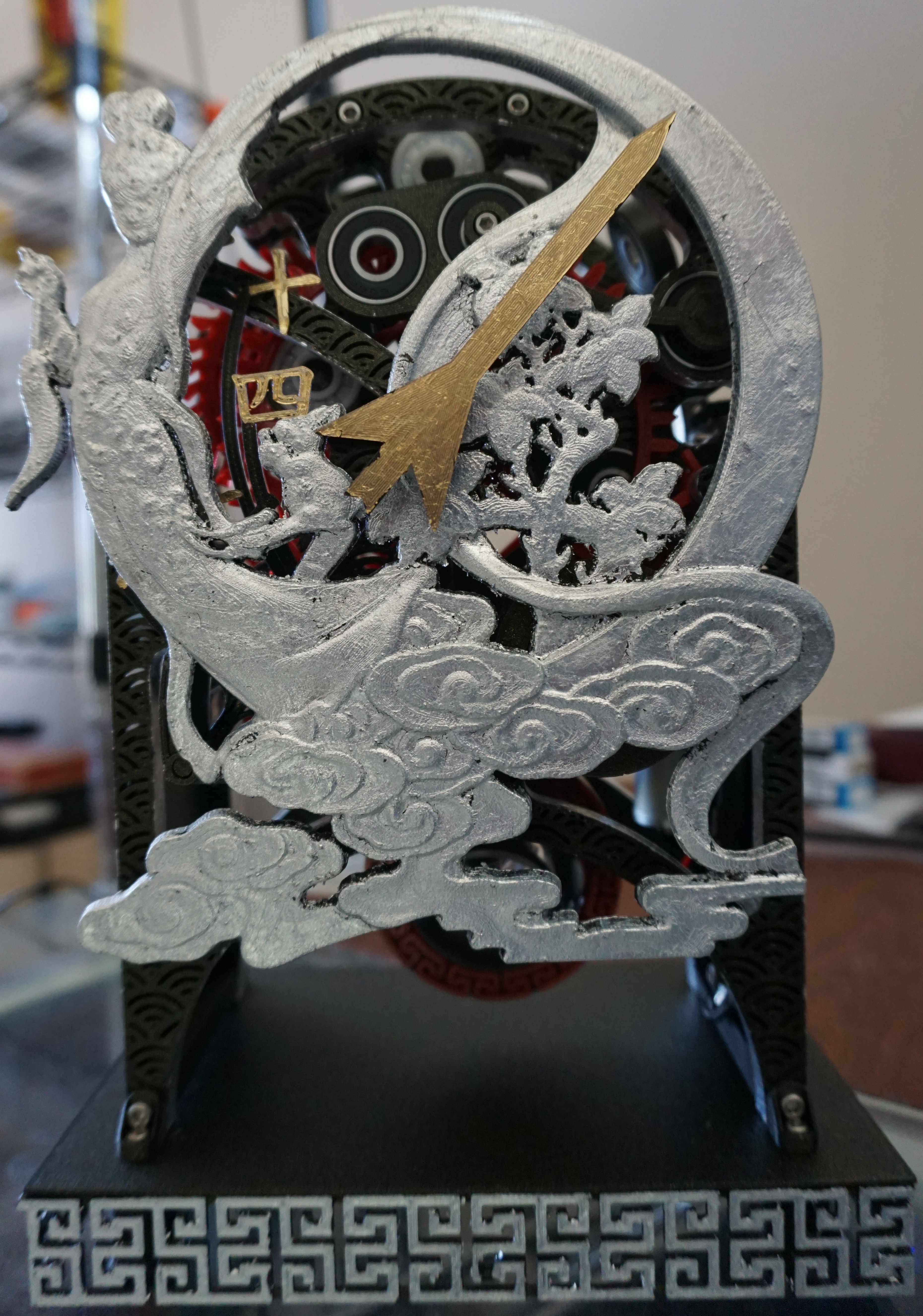
Without further ado, here is the front view of the finished clock (click for full resolution):
The Face and Time Display
The most striking feature of the clock is its unique face plate and time display.
The face plate itself is not my artwork. It is adapted from a model by stronghero on Thingiverse.
I did not originally intend to go with a Chinese theme for the clock. I did, however, want a unique face. I spent several weeks going through various unconventional display designs, including a system for producing the hour label through Moiré patterns in an otherwise inscrutable face pattern. At the same time, I was thinking of ways it might be possible to actually print that model. At some point, it occurred to me that the model itself is largely round with an open view through the inside, while also having a support that cuts through the centre of that circle. It was perfect for a clock face. The Chinese theme in general fell out from there.
The face plate itself is a model of Chang’e, a figure of Chinese mythology who came to live on the moon after drinking an elixir of immortality. Her husband, Houyi, was an archer, represented by the arrow-like shape of the minute hand.
The time display itself is also unusual, though not entirely unique, in that it only has one hand. This is the minute hand. The current hour (1 through 24) is shown in Chinese numerals behind the left side of the plate. In the image above, the current time is 14:05. This is a jump hour mechanism: the hour display remains motionless until the minute hand crosses the 60-minute mark, at which point it abruptly “jumps” to the next hour.
Body Structure
The body of the clock has an open design revealing all the inner workings, making it a skeleton clock. All the functional parts are contained in distinct layers between five frame plates and the face plate.
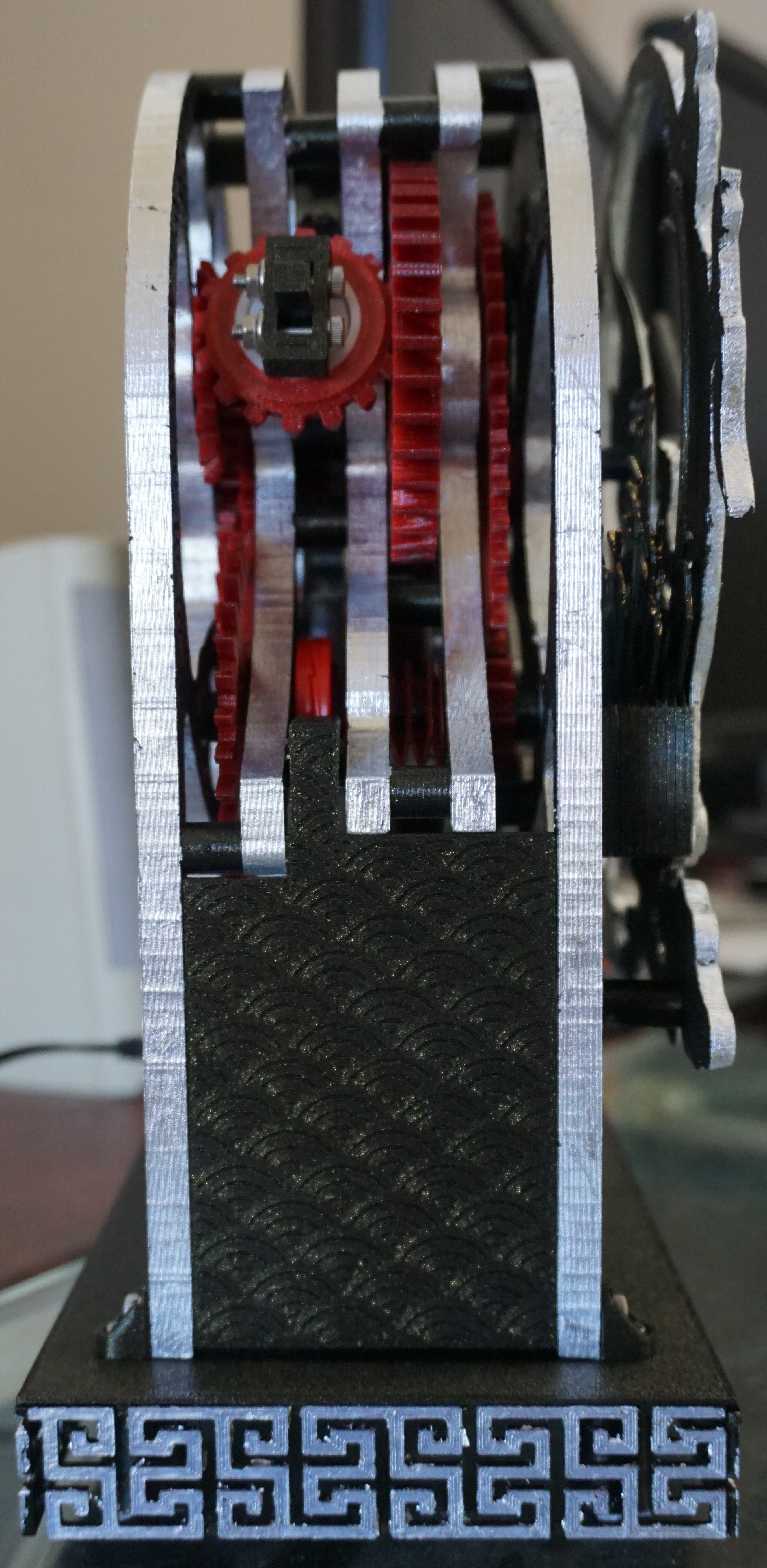
As you can see, there’s a additional side plate on each side, which in this view obscures the pendulum. The reason for this is that the right side needs something to hide the electrical components which are otherwise quite an eyesore. The left side plate is present only for symmetry. This does unfortunately reduce the amount of light that can reach the pendulum, making it a bit hard to see in detail from the front.
Time Keeping
Here’s where some technical details start. As I mentioned earlier, a deep dive onto the mechanisms will happen in later posts, so this section assumes some familiarity with clockwork.
Time keeping is handled by a pendulum and a deadbeat escapement, which is only unusual due to the escape wheel (in the side view, the wide gear parallel to most of the others) being off-centre. The escapement runs at an unusual 2.4Hz or 144 bpm (i.e., it ticks 2.4 times per second).
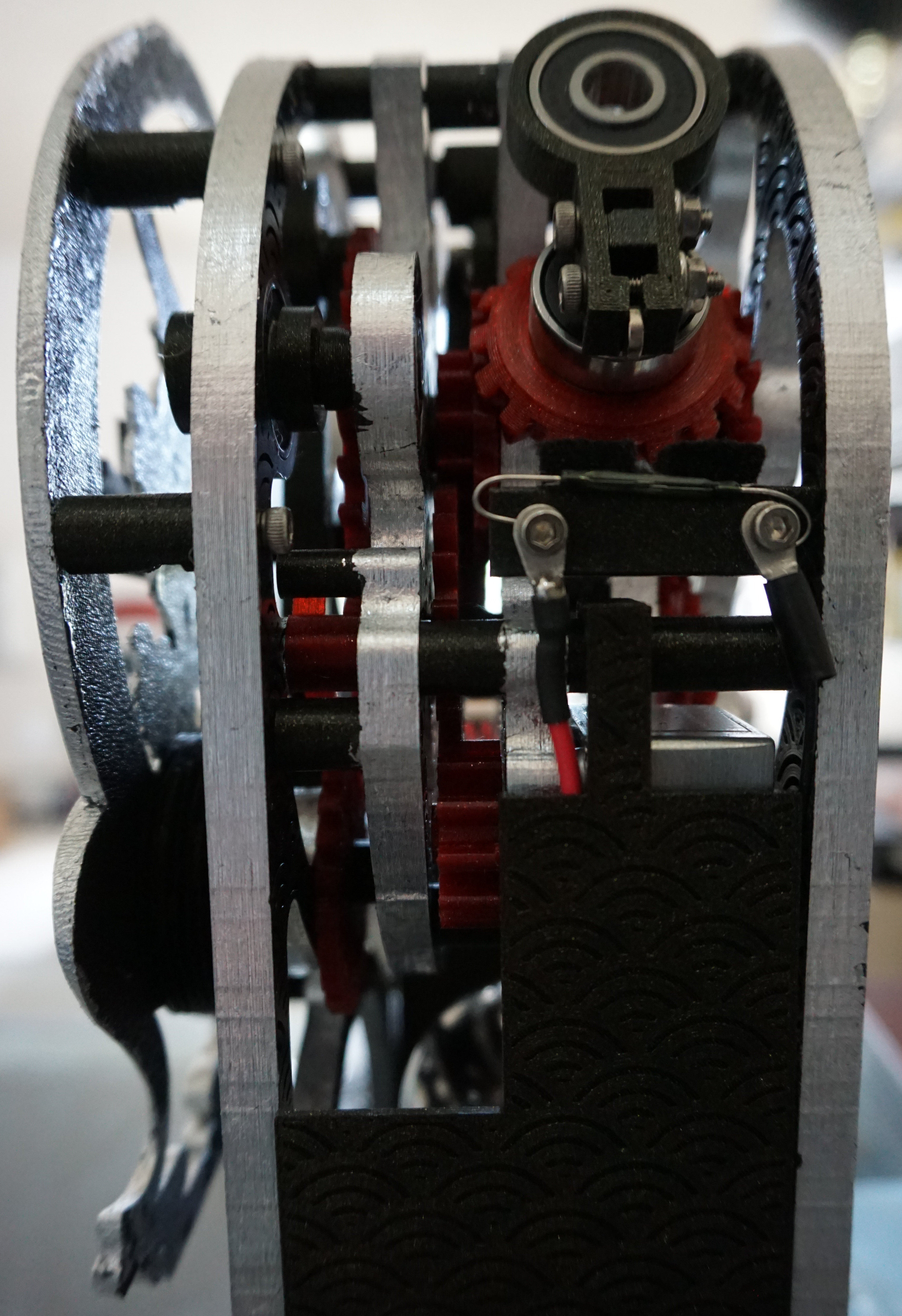
The time keeping system is isolated from the rest of the clock by a direct differential remontoire. This means that generally only the pendulum, the escape wheel, and the bevel gear visible in the side view above are moving. Once every 12 seconds, the remontoire triggers and advances the rest of the clock 12 seconds forward. This includes the minute hand: instead of moving a tiny bit every tick, it moves forward one fifth of a minute every 12 seconds.
This regime has two major benefits. One, the force driving the escapement and pendulum can be kept quite small; here, it is simply the weight of the bearing on that bevel gear. Second, it ensures that friction and other resistance effects in the rest of the clock do not impact the time keeping. This both helps precision and makes it much easier to identify the source of mechanical problems.
Overall, the time keeping system is very accurate. Almost. Other than an unexpected issue described in Room for improvement, it keeps time very precisely, though I’m not currently able to quantify that statement.
Power Supply
There are two general ways to power a purely mechanical clock.
Weights. This is most commonly seen in grandfather clocks. However, weights don’t really work for a desk clock: There is neither the space for the weights themselves nor any meaningful distance for them to descend.
A mainspring. This takes the form of a large coil spring which gets wound inside a barrel. Mainsprings with any substantial energy capacity tend to be a bit dangerous though, and require the barrel to be able to withstand their force, so this approach was not really something I was willing to consider.
As both pure-mechanical options are out, this clock is not purely mechanical. Instead, when the remontoire triggers, an electric motor driven by a 5-Volt power supply is used to drive the clock.
The motor itself is controlled mechanically. A second differential on the right side of the clock has a small weight and falls when the remontoire triggers. A small magnet on the differential causes a reed switch to close, starting the motor. When the remontoire cycle completes, the mechanism locks and the differential rises, re-opening the circuit.
Materials
All non off-the-shelf parts are 3D printed by a Prusa i3 MK3 printer, and as such are plastic. Most parts are printed from PLA (specifically, Filamentum Vertigo Galaxy, the black colour with the gold-ish sheen visible in the photos). The gears and pendulum decoration are PETG (specifically, Prusament Carmine Red), primarily for the visual aspect that PETG’s natural translucency brings. Two parts are printed in ABS in order to be vapour-smoothed with acetone.
All in all, there over 90 3D printed parts, not including spacers.
The gold and silver parts were accomplished by gilding, i.e., the application of (imitation) metal leaf to the parts. This turns out to be something I’m rather inept at, at least currently, so I wouldn’t say this aspect came out fantastically. I ultimately decided to just run with the somewhat antiqued look that came with the imperfect results.
There are of course a decent number of non-3D-printed parts. The pendulum bob is a 2-inch steel bearing ball. The clock is held together by around 50 M3 screws and contains 34 skate bearings of a few different types to allow it to run smoothly. Felt is used in a couple places for noise reduction. Finally, there’s of course the electric motor and other electrical components.
Room for improvement
There are a few issues I did not become aware of until after having “finished” the clock.
As you can probably see in the earlier images, the face plate slightly obscures some of the digits, particularly the lower parts of 七 and 九. This is a result of a last-minute change in how the face plate was handled. Originally, I had a “2.5D” face plate wherein I had simply traced the original model into 7 two-dimensional layers. Near the end of the project, I found a way to actually get a fully 3D version of the model imported into OpenSCAD, and went with that. Unfortunately, the new model is a few percent smaller than it should be, and also positioned around a centimetre higher than it should be. I will probably address this later. It’s a simple fix but will take a while to actually make the new part.
It may have been better to mount the reed switch on the inside of the right side plate, which would both hide it and make wiring the electricals easier.
A more substantial issue than both of these is also one that was very unexpected (to me, at least): thermal expansion. A 100μm change in the pendulum length corresponds to around a 140 second/week speed difference. With the pendulum being around 20cm long (measured to the bottom, not the centre of gravity) and made of PLA, it only takes a 6°C temperature difference to effect such a length change.
That might not be a problem if the clock is to be run in an environment with a very stable temperature, but my apartment is not such an environment. While I was trying to tune the exact pendulum length via its adjustment screw, I noticed that the clock had suddenly started speeding up, seemingly on its own. Over the course of a couple days, it sped up from a gain of ~4 minutes/week to ~7 minutes/week. After a while, I finally realised this correlated to a drop in indoor temperature from ~27°C to ~17°C. The predicted change in speed due to thermal contraction roughly matches the observed change in speed, so I am reasonably confident that is the main issue. The solution will likely be some sort of Gridiron-like approach with alternating PLA and ABS, but I have yet to design that.